
A New Concept of the Universe by Walter Russell
via Walter Russell.
A New Concept of the Universe by Walter Russell
via Walter Russell.
A Marx generator is an electrical circuit first described by Erwin Otto Marx in 1924. Its purpose is to generate a high-voltage pulse. Marx generators are often used to simulate the effects of lightning on power line gear and aviation equipment. A bank of 36 Marx generators is used by Sandia National Laboratories to generate X-rays in their Z Machine.

A number of capacitors are charged in parallel to a given voltage, V, and then connected in series by spark gap switches, ideally producing a voltage ofV multiplied by the number, n, of capacitors (orstages). Due to various practical constraints, the output voltage is somewhat less than n×V.
Proper performance depends upon selection of capacitor and the timing of the discharge. Switching times can be improved by doping of the electrodes with radioactive isotopes caesium 137 or nickel 63, and by orienting the spark gaps so that ultraviolet light from a firing spark gap switch illuminates the remaining open spark gaps.[1] Insulation of the high voltages produced is often accomplished by immersing the Marx generator in transformer oil or a high pressure electronegative gas such as sulfur hexafluoride (SF6).
Note that the less resistance there is between the capacitor and the charging power supply, the faster it will charge. Thus, in this design, those closer to the power supply will charge quicker than those farther away. If the generator is allowed to charge long enough, all capacitors will attain the same voltage.
In the ideal case, the closing of the switch closest to the charging power supply applies a voltage 2Vto the second switch. This switch will then close, applying a voltage 3V to the third switch. This switch will then close, resulting in a cascade down the generator that produces nV at the generator output (again, only in the ideal case).
The first switch may be allowed to spontaneously break down (sometimes called a self break) during charging if the absolute timing of the output pulse is unimportant. However, it is usually intentionally triggered once all the capacitors in the Marx bank have reached full charge, either by reducing the gap distance, by pulsing an additional trigger electrode (such as a Trigatron), by ionising the air in the gap using a pulsed laser, or by reducing the air pressure within the gap.
The charging resistors, Rc, need to be properly sized for both charging and discharging. They are sometimes replaced with inductors for improved efficiency and faster charging. In many generators the resistors are made from plastic or glass tubing filled with dilute copper sulfate solution. These liquid resistors overcome many of the problems experienced by more-conventional solid resistive materials, which have a tendency to lower their resistance over time under high voltage conditions.
The Marx generator is also used to generate short high-power pulses for Pockels cells, driving a TEA laser, ignition of the conventional explosive of a nuclear weapon, and radar pulses.
Shortness is relative, as the switching time of even high-speed versions is not less than 1 ns, and thus many low-power electronic devices are faster. In the design of high-speed circuits, electrodynamics is important, and the Marx generator supports this insofar as it uses short thick leads between its components, but the design is nevertheless essentially an electrostatic one. (In electrodynamic terms, when the first stage breaks down it creates a spherical electromagnetic wave whose electric field vector is opposed to the static high voltage. This moving electromagnetic field has the wrong orientation to trigger the next stage, and may even reach the load; such noise in front of the edge is undesirable in many switching applications. If the generator is inside a tube of (say) 1 m diameter, it requires around 10 wave reflections for the field to settle to static conditions, which restricts pulse leading edge width to 30 ns or more. Smaller devices are of course faster.) When the first gap breaks down, pure electrostatic theory predicts that the voltage across all stages rises. However, stages are coupled capacitively to ground and serially to each other, and thus each stage encounters a voltage rise that is increasingly weaker the further the stage is from the switching one; the adjacent stage to the switching one therefore encounters the largest voltage rise, and thus switches in turn. As more stages switch, the voltage rise to the remainder increases, which speeds up their operation. Thus a voltage rise fed into the first stage becomes amplified and steepened at the same time.
The speed of a switch is determined by the speed of the charge carriers, which gets higher with higher voltage, and by the current available to charge the inevitable parasitic capacity. In solid-state avalanche devices, a high voltage automatically leads to high current. Because the high voltage is applied only for a short time, solid-state switches will not heat up excessively. As compensation for the higher voltages encountered, the later stages have to carry lower charge too. Stage cooling and capacitor recharging also go well together.

To deliver 5 ns rise time pulses, the Marx generator is often built into a coaxial wave guide. The spark gaps are placed as close as possible together for maximum UV light exchange for minimum jitter. DC HV comes from underneath, pulsed HV leaves at the top into the coaxial line. The double line of spheres in the middle are the spark gaps, all other spheres are to avoid corona discharge. Blue=water capacitor. Grey=solid metal. Black= thin wire. The outer conductor also functions as a vessel, so that the gas and the pressure can be optimized.
Avalanche diodes can replace the spark gap for stage voltages less than 500 volts. The charge carriers easily leave the electrodes, so no extra ionisation is needed and jitter is low. The diodes also have a longer lifetime than spark gaps.
A speedy switching device is an NPN avalanche transistor fitted with a coil between base and emitter. The transistor is initially switched off and about 300 volts exists across its collector-base junction. This voltage is high enough that a charge carrier in this region can create more carriers by impact ionisation, but the probability is too low to form a proper avalanche; instead a somewhat noisy leakage current flows. When the preceding stage switches, the emitter-base junction is pushed into forward bias and the collector-base junction enters full avalanche mode, so charge carriers injected into the collector-base region multiply in a chain reaction. Once the Marx generator has completely fired, voltages everywhere drop, each switch avalanche stops, its matched coil puts its base-emitter junction into reverse bias, and the low static field allows remaining charge carriers to drain out of its collector-base junction.
One application is so-called boxcar switching of a Pockels cell. Four Marx generators are used, each of the two electrodes of the Pockels cell being connected to a positive pulse generator and a negative pulse generator. Two generators of opposite polarity, one on each electrode, are first fired to charge the Pockels cell into one polarity. This will also partly charge the other two generators but not trigger them, because they have been only partly charged beforehand. Leakage through the Marx resistors needs to be compensated by a small bias current through the generator. At the trailing edge of the boxcar, the two other generators are fired to “reverse” the cell.
Marx generators are used to provide high-voltage pulses for the testing of insulation of electrical apparatus such as large power transformers, or insulators used for supporting power transmission lines. Voltages applied may exceed 2 million volts for high-voltage apparatus.
That’s O.K., but what took them so long? You can’t really blame them for being so suddenly astounded, considering the long and thorough eradication of Tesla’s name from encyclopedias and books on science, invention and technology.
The conspicuous vacuum created where the mention of Tesla should have been, as one who made such important contributions to science, technology, and the quality of our lives, raises ominous questions as to why his memory became virtually stricken from history almost the day after his death. What did Tesla discover which threatened the powers that be? Since we already know about the many patented inventions, my assumption has always been that the unknown, still classified works were far in advance of the published ones, and were in realization of projects about which Tesla had announced he was working on, or had already tested and developed, but had not yet “…given to the world”.
We know from available documentation and reliable sources that these discoveries and developments were realized by Tesla before his death, yet are still classified. Among his many patented inventions, numerous startling discoveries and surprises have been recently found by researchers and experimenters, which show in retrospect that his claims were modest.
Tesla was born in Smiljan, Lika, Austro-Hungary (now Serbia), in 1856, and died Jan. 3, 1943 in New York City. An early biography, Prodigal Genius, the Life of Nikola Tesla, by John J. O’Neill, was initially published three times in November, 1944. In case you are wondering, the three publishings in the same month were not due to landslide sales at the bookstores, but rather to O’Neill’s having been threatened and censored by the FBI, and forced to republish several times because of their deletion and censoring of material which to this day is still classified. It was odd, given Tesla’s repeatedly unsuccessful efforts to get the attention of the war department, met with ignorance and shoddy treatment. It was not until after it came to their attention in 1942, that the Nazis were building flying saucers and other ‘fantasy’ weapons based on Tesla’s inventions, that the U. S. Government became so concerned.
In the case of (flying saucer) electro-propulsion, this invention is not only classified, but the very existence of it is categorically denied by the government, while its covert agents in the UFOlogy community attribute it to extraterrestrial, “alien” origins. What better way to deter civilian scientific investigation into the obvious?I first heard of Tesla in 1943, as a child of four, when his death was lamented by Elmer Schlosser, a neighborhood adult friend who first told me about him. I also once had in my collection of old books, a well-preserved, beautiful old commemorative book issued by the 1893 Chicago World’s Fair — the Columbian Exposition —which featured Tesla as its honored guest.
There were numerous photos of Tesla’s inventions and some articles. Today, over 54 years after Tesla’s death, experimenters are still conducting exciting and trail-blazing experiments with Tesla’s discoveries of over 100 years ago, and continuing to find ‘hidden’ meanings in some of his early writings and patents.There have been countless speculations as to what Tesla’s most secret discoveries were. At the time of his death, there were in all, the approximate equivalent of a railroad boxcar load of Tesla materials confiscated by the FBI, from around four different storage locations and Tesla’s hotel storage and hotel room and safe. Of this, a total of only about 150,000 documents were released to Tesla’s Yugoslavian relatives, now held by the Tesla Institute in Belgrade.
These documents and old models, primarily of a historical nature, comprise most of the published Tesla materials of the institute. The huge volume of the rest of the documents and models was retained by the Custodian of Alien Properties in an unclassified state, because the government’s “experts” had declared that none of it was worth classifying, from 1943 until 1945, when, following the arrival of the Nazi scientists and the secret war files of Nazi Germany, acquired under Operation Paperclip, the spooks from Wright-Patterson Air Force Base hurried up to the warehouses of the Custodian of Alien Properties, and took possession of all the documents and other materials, and every bit of them have been classified at the highest level ever since, the government having declassified NONE of them.
The remainder of Tesla’s papers are still classified — literally tons of notes, documents, drawings, and plans. The government distributed false rumors that “Tesla never kept notes”, which was a blatant lie. The notes on his Colorado Springs experiments alone (1899-1900) were enough for a large-format book of 433 pages. Considering the fact that Tesla continued to do some mysterious research at the Colorado Springs laboratory for a number of years—from which we have no notes—there is ample cause for suspicion. It is known from Tesla’s own word’s that these additional experiments at Colorado Springs were much more far-reaching.
In 1979, when I tried to gain access to Tesla papers held at the J. Robert Oppenheimer Study Center, at LANL (“Los Alamos National Lab), the government admitted possession, but denied access for lack of the appropriate “badge” (security clearance). Tesla’s papers are now held at least in part, in Los Alamos, New Mexico. On that same day, I found the hydrogen bomb plans on the public access shelves, yet was denied access to Tesla’s papers. What could be more sensitive than the hydrogen bomb, which was invented by Tesla prior to 1943?After the war, in 1946, at age 8, when our family returned to the little west Texas town of Kermit, I visited the radio shop of my old friend, Elmer Schlosser, and lugged home a pile of salvaged electronic components he gave to me, after a savvy little Tesla talk.
I assembled the components, ran a ground line up a tree, placed my newly assembled device in my tree house, erected an antenna constructed of screen wire, and attempted to ‘radio in’ some power. Unsuccessful, I nonetheless continued my experiments with electromagnetism for eight more years, until I set them aside for twenty years. In 1975, I resumed my “Tesla project”, eventually built a number of Tesla coils, and even began giving some lectures and demonstrations in the Santa Fe area to small gatherings.In late 1974, the CIA had commenced a pattern of harassment originally intended to “motivate” me to accept an executive position later offered to me by George Bush, in early 1975. I rejected the offer and immersed myself deeply in intense research, and the harassment continued and intensified so much that it finally brought my research to a temporary standstill between 1986 and 1992, which provoked the first publication of my book, Space Aliens From the Pentagon, in 1993.
I issued a revised and expanded second edition in late 1995. Another of my books, Occult Ether Physics: Tesla’s Hidden Space Propulsion System and the Conspiracy to Conceal It, concentrates on the 19th century “aether” science leading up to Tesla’s discovery of electro-propulsion, and I also include a couple of astounding Relativity-destroying “free-energy” re-discoveries.Tesla’s holy grail was to build his “electric flying machine”, and to draw some of the “environmental energy” out of the cosmos. This plan involved a theory of radioactivity under development by Tesla in the 1890s, which entirely presaged and conflicted with currently accepted Relativism, quantum mechanics, and nuclear energy theories. (This is not to say that something called “classical quantum mechanics” may not be valid, as I distinguish it from “Relativist quantum mechanics”).
To Tesla, so-called “atomic energy” was in fact the result of “environmental energy” emanating from the cosmos, and made known to us via “radioactive” matter, which he said had the peculiar property of resonating and reacting with ubiquitous “cosmic radiation” (a term used by Tesla before 1900).The “cosmic radiation” of which Tesla spoke was of much higher frequency than what we call “radioactive emanations”, which to Tesla were the result of a “step-down” process, in which certain peculiar matter reacts to and converts ubiquitous, omnidirectional cosmic radiation—which today we call “zero point radiation” (“ZPR”)—from higher frequencies, to lower, more useful and appropriate frequencies, such as gamma, x-ray, ultraviolet, visible, infrared radiation, as well as magnetism and even electrical current. These step-down frequencies are much easier to detect and measure than the ZPR.
The existence of the ZPR was well known to Tesla in the 1890s, but it was not until recently that it became scientifically accepted as a proven fact. This radiation is of such high frequency that it normally passes through space, the earth, and our bodies without harm or incident, in constant equilibrium, because its short wavelengths do not normally react or resonate with the atoms of most matter. It is so-called “radioactive matter” — according to Tesla — which has a peculiar atomic structure which reacts with this radiation to produce “radioactivity”. “Atomic energy”, to Tesla, comes from the ZPR, not atoms. If a lump of radium, for example, could be shielded from the effects of the ZPR, said Tesla, it would no longer show radioactivity.Most naturally radioactive elements are dense and “unstable”—that is, they are said by the Relativists to “decay” as radiation is emitted, to elements of lower atomic numbers.
The Relativists—with whom Tesla vehemently disagreed—believe that naturally radioactive elements spontaneously lose mass in the process of such “decay”, so that the energy released as radioactivity, is equivalent to the lost mass according to Einstein’s equation, E = MC2. This always seemed untenable to me, since such elements would have to have been, by the related cosmological myth of the “Big Bang”, older than the earth, yet geological examination shows that they are found to have evolved through physical processes which have occurred within natural structures here on earth. If such elements had been part of the alleged Big Bang, they would have fully “decayed” before now.
On the other hand, if such elements are in the process of being continually evolved by natural conditions within earth, as well as in outer space, through electrical, magnetic and other physical forces, the reasons for their presence is more reasonable. I don’t think this is any surprise to the “national security” elite. Something else is going on, and someone else knows it.If non-radioactive elements are converted into radioactive ones by the forces of nature, what are these processes? In aNew York Times article of July 11, 1937 (pg. 13, col.2), in one of Tesla’s famous birthday announcements, Tesla stated that he had developed a process for the “manufacture” of radium (transmutation from other elements), which was so efficient that it could be sold for $l.00 per pound. He also announced that he had “absolutely developed” a system for the interstellar transmission of energy.
He said he had been working in “several laboratories”, but refused to disclose their locations. His working model, he said, “…employs more than three dozen of my inventions. It is a complex apparatus, an agglomeration of parts.” It could convey “…several thousand units of horsepower to other planets, regardless of the distance”, traveling “…through a channel of less than one-half of one-millionth of a centimeter.” Further, he said, “…it is not an experiment. I have built, demonstrated and used it. Only a little time will pass before I can give it to the world.”That time never came. In less than six years, his death occurred in the presence of two FBI agents and a German nurse, and the Nazis had had his plans under active development since as early as 1936.
These facts demonstrate that even in his 80s, in 1937, Tesla was involved in secret research at several undisclosed laboratories, on technology which today remains highly classified, yet neither the general public nor anyone at the International Tesla Society seems to have any idea as to the details, because they have been concealed from us by the “powers that be”. Through some ingenious investigating, it is possible to reconstruct some of the facts. In focusing on just Tesla’s publicly available technology, it is obvious that, even in it, there is the air of the fantastic, the almost incredible. Taking this a step further, it is possible to reconstruct much of the unknown Tesla discoveries from publicly-available sources, in order to see what has been carefully hidden from us by our own government and the corporate fascists who control it.
Stay updated on Tesla’s technology at FreeEnergyCommunity.com
Supported by the Pierce-Arrow Co. and General Electric in 1931, Nikola Tesla, inventor of the AC generator, took the gasoline engine from a new Pierce-Arrow and replaced it with an 80-horsepower AC electric motor with no external power source.
Tesla reportedly bought 12 vacuum tubes, some wires and assorted resistors, and assembled them in a circuit box 24 inches long, 12 inches wide and 6 inches high, with a pair of 3-inch rods sticking out. Getting into the car with the circuit box in the front seat beside him, he pushed the rods in and announced, “We now have power”. Using no gasoline whatsoever Tesla proceeded to drive the car for a week and at speeds of up to 90 mph.
As the AC motor can only operate on AC (alternating current that is typically supplied in a home) electricity the single 12 volt car battery wasn’t the source of power as a car battery supplies only DC (direct current) electricity. So what was the source of power that powered the AC electric motor? Electromagnetic (EM) waves which Tesla declared is a free source of power that is “everywhere present in unlimited quantities”.
The 1931 Pierce Arrow demonstration proved beyond a shadow of a doubt that we don’t need any gasoline whatsoever to power our automobiles. Again, this was in 1930!!! 81 years of cancer causing, healthcare ensuring, oil polluting BS!
When will we as a united people stand up for ourselves, start leading the way into the future? We the People DEMAND these alternative technologies be unsuppressed! The time is now, and I – Michael Alexander, will stop at nothing until such a feat is accomplished.

First and foremost is the absolute silence one experiences when riding in an electrically powered vehicle. There is not even a hint of noise. One simply turns a key and steps on the accelerator – the vehicle moves instantly! No cranking from the start, no pumping of the accelerator, no spark control to advance, no exhaust pipes, no leaking gas tanks, no clogged fuel pumps or lines, zero emissions and no tuneups. One simply turned the ignition switch to on!
Second, is a sense of power. If one wants to increase speed, you simply depress the accelerator further – there is never any hesitation. Releasing the accelerator causes the vehicle to slow down immediately – you are always in complete control.
Thirdly, the electric cars envisioned by Tesla were a lot lighter as there were no battery packs (only a single 12 volt battery was used to power the lights), no gas tank with heavy liquid gasoline or diesel, no exhaust system (no muffle, catalytic converter, or pipes) and no heavy combustion engine.
Lastly and most importantly the source of power for his vehicle is available for free. You would never have to recharge this vehicle. You would never have to pay 1¢ to any electrical company. Since the source of energy that powered Tesla’s electric car in 1931 was energy harvested from EM waves that is everywhere this type of electric car had unlimited range.
Tesla used an antenna to capture this free energy and he was able to drive for hours with no stopping whatsoever for a recharge. If he drove and ended up in the middle of nowhere he could stop and rest and continue on in a couple of hours or even days without ever having to worry about running out of power.
It is not difficult to understand why these vehicles were so very popular around the turn of the century. It is now obvious why the electric car was killed 80 years ago. The was no money to be made by the oil companies nor the electric companies. Even government couldn’t make money from this type of electric car. With gas powered cars the government could charge a tax on every gallon of gasoline or diesel. Freely available electromagnetic energy could not be metered and therefore taxed.

It was a Pierce Arrow, one of the luxury cars of the period. The engine had been removed, leaving the clutch, gearbox and transmission to the rear wheels undisturbed. The gasoline engine had been replaced with a round, completely enclosed electric motor of approximately 1m in length and 65cm in diameter, with a cooling fan in front. Reputedly, it has no distributor. Tesla was not willing to say who had manufactured the engine. It was possibly one of the divisions of Westinghouse.
The “energy receiver” (gravitational energy converter) had been built by Tesla himself. The dimensions of the converter housing were approximately 60 x 25 x 15cm. It was installed in front of the dashboard. Among other things, the converter contained 12 vacuum tubes, of which three were of the 70-L-7 type. A heavy antenna approximately 1.8 meters long, came out of the converter. This antenna apparently had the same function as that on the Moray converter. Furthermore, two thick rods protruded approximately 10cm from the converter housing.Tesla pushed them in saying “Now we have power.” The motor achieved a maximum of 1800rpm. Tesla said it was fairly hot when operating, and therefore a cooling fan was required. For the rest, he said there was enough power in the converter to illuminate an entire house, besides running the car engine. The car was tested for a week, reaching a top speed of 90 miles per hour effortlessly. Its performance data were at least comparable to those of an automobile using gasoline. At a stop sign, a passerby remarked that there were no exhaust gasses coming from the exhaust pipe. Petar answered “We have no motor.” The car was kept on a farm, perhaps 20 miles outside of Buffalo, not far from Niagara Falls.
A few months after this automobile test, and because of the economic crisis at the time, Pierce Arrow had to stop production. It is very likely that the interconnection between the electric motor and the transmission had been performed there. Pierce Arrow’s tools were taken over by Studebaker, in South Bend. Not quite 30 years later, that company also vanished to form American Motors, jointly with Nash. Later, some of its fans attempted to resuscitate the Pierce Arrow. Unfortunately, they were not successful.Thus, today that company’s name is in a mausoleum, together with others, such as Horch, Maybach, Hispano-Suiza, Bugatti and Isotta Fraschini. From LINK`http`waterpoweredcar.com/teslascar.html“LINK
In light of a report that Tesla did not have a nephew by the name of Peter Savo, the radiant-energy powered Pierce Arrow account must be taken with a degree of skepticism. A number web pages exist that serve to perpetuate the anecdote. Every account of this purported demonstration auto is based upon a story supposedly told to a “Derek Ahlers,” plus what appears to be literary embellishment.
Tesla did assert that his system for the wireless transmission of electrical energy could be used for the propulsion of aircraft and ships at sea. Writing to Benjamin F. Miessner in 1915 he stated,
“In an article in the Century Magazine . . . I have related the circumstances which led me to develop the idea of a self-propelled automaton. My experiments were begun sometime in ’92 and from that period, on, until ’95, in my laboratory at 35 South Fifth Avenue, I exhibited a number of contrivances and perfected plans for several complete automata. After the destruction of my laboratory by fire in ’95, there was an interruption in these labors which, however, were resumed in ’96 in my new laboratory at 46 Houston Street where I made more striking demonstrations, in many instances actually transmitting the whole motive energy to the devices instead of simply controlling the same from a distance. . . . [Nikola Tesla — Guided Weapons & Computer Technology, pp. 227-229.]
In the article “Nikola Tesla Tells How We May Fly Eight Miles High at 1,000 Miles an Hour” (Reconstruction, July 1919) he spoke about a possible technological revolution in the transmission of propulsive power to aircraft “through the air.”
For years I have advocated my system of wireless transmission of power which is now perfectly practicable and I am looking confidently to its adoption and further development. In the system I have developed, distance is of absolutely no consequence. That is to say, a Zeppelin vessel would receive the same power whether it was 12,000 miles away or immediately above the power plant. The application of wireless power for aerial propulsion will do away with a great deal of complication and waste, and it is difficult to imagine that a more perfect means will ever be found to transport human beings to great distances economically. The power supply is virtually unlimited, as any number of power plants can be operated together, supplying energy to airships just as trains running on tracks are now supplied with electrical energy through rails or wires.
The transmission of power by wireless will do away with the present necessity for carrying fuel on the airplane or airship. The motors of the plane or airship will be energized by this transmitted power, and there will be no such thing as a limitation on their radius of action, since they can pick up power at any point on the globe.
The advance of science to this point, however, is attended with terrible risks for the world. We are facing a condition that is positively appalling if we ever permit warfare to invade the earth again. For up to the present war the main destructive force was provided by guns which are limited by the size of the projectile and the distance it can be thrown. In the future nations will fight each other thousands of miles apart. No soldier will see his enemy. In fact future war will not be conducted by men directly but by the forces which if let loose may well destroy civilization completely. If war comes again, I look for the extensive use of self-propelled air vehicles carrying enormous charges of explosive which will be sent from any point to another to do their destructive work, with no human being aboard to guide them. The distance to which they can be sent is practically unlimited and the amount of explosive they can carry is likewise practically unlimited. It is practicable to send such an air vessel say to a distance of four or five thousand miles and so control its course either gyroscopically or electrically that it will land at the exact spot where it is intended to have it land, within a few feet, and its cargo of explosive can there be detonated.
“This cannot be done by means of the present wireless plants, but with a proper plant it can be done. and we have here the appalling prospect of a war between nations at a distance of thousands of miles, with weapons so destructive and demoralizing that the world could not endure them. That is why there must be no more war.”
In the article “Faster Liners is Tesla’s Dream” (New York Sun, June 5, 1935) he spoke about the transmission of propulsive power to ships at sea “through the stratosphere.”
The principles of this high tension power, generated by shore plants and transmitted through the upper reaches of the air, illuminating the sky, turning night into day and at the same time supplying power, have occupied Dr. Tesla’s attention on and off now for the past thirty-five years. . . .
“There is a method of conveying great power to ships at sea which would be able to propel them across oceans at high speed. . . .
“The principle is this. A ray of great ionizing power is used to give to the atmosphere great powers of conduction. A high tension current of 10,000,000 to 12,000,000 volts is then passed along the ray to the upper strata of the air, which strata can be broken down very readily and will conduct electricity very well.
“A ship would have to have equipment for producing a similar ionizing ray. The current which has passed through the stratosphere will strike this ray, travel down it and pass into the engines which propel the ship.”
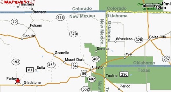
An article appearing in the New York Daily News, April 2, 1934 titled “Tesla’s Wireless Power Dream Nears Reality” mentions the planned “test run of a motor car [for a distance of 30 or 40 miles] over a stretch of [Atchison, Topeka and Santa Fe] railway track [running from Boise City, Oklahoma] to Farley, N. M.” using wireless transmission of electrical energy to power the vehicle. The equipment was assembled by “two Californians” and is described as “including a high-powered radio transmitter with big coils and and short antenna.”

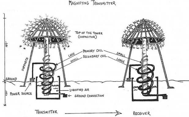
It’s not generally known, but Tesla actually had two huge magnifying transmitters built in Canada, and [Arthur] Mathews operated one of them. . . . People mostly know about the Colorado Springs transmitters and the unfinished one on Long Island. I saw the two Canadian transmitters personally on my trip last year. All the evidence is there. . . .
In 1922 Tesla spoke about the application of wireless transmission to transportation systems.
Question : Will not wireless transmission of energy result in time in the moving of practically all means of transportation with electrical energy from central power stations?
MR. TESLA : No, I do not expect that such will be the case, for the transportation systems now used present certain important practical advantages which cannot be disregarded.
Question: Will not automobiles, for instance, be operated merely by the operative “cutting in” on electrical energy supplied by wireless from power stations?
MR. TESLA : I fear we shall not live to see the wireless system in general use for this purpose. It is difficult to propel an automobile by the new method for reasons with which experts are familiar. Success can be much more easily achieved in the case of airships.
In time to come it is possible that some form of automobile may be perfected that will enable this propulsion of such vehicles to be effected by power drawn from the ambient medium. [Glass, J. P. , “Tremendous Possibilities of Radio, An Interview With Nikola Tesla,” Radio News, November 1922.] From LINK`http`www.tfcbooks.com/teslafaq/q&a_016.htm“LINK
Tesla had already considered the condition of charged particles, each representing a tightly constricted whorl of aether. The force necessarily exerted at close distances by such aetheric constrictions was incalculably large. Aetheric ponderance maintained particulate stability. Crystalline lattices were therefore places within which one could expect to find unexpected voltages. Indeed, the high voltages inherent in certain metallic lattices, intra-atomic field energies, are enormous. The close Coulomb gradient between atomic centers are electrostatic potentials reaching humanly unattainable levels. By comparison, the voltages which Tesla once succeeded in releasing were quite insignificant. In these balanced lattices, Tesla sought the voltages needed to initiate directed aetheric streams in matter. Once such a flow began, one could simply tap the stream for power.In certain materials, these ether streams might automatically produce the contaminating electrons, a source of energy for existing appliances.
One could theoretically then “tailor” the materials needed to produce unexpected aetheric power with or without the attendant detrimental particles. Tesla did mention the latent aetheric power of charged forces, the explosive potentials of bound Ether, and the aetheric power inherent in matter. By these studies, Tesla sought replacement for the 100,000,000 volt initiating pulses which natural law required for the implementation of space Ether. Tesla had long been forced to abandon those gigantic means by other, less natural laws. Thereafter, Tesla shifted his attentions from the appreciation of the gigantic to an appreciation of the miniature. He sought a means for proliferating an immense number of small and compact aether power receivers. With one such device, Tesla succeeded in obtaining power to drive am electric car.
But for the exceptional account which follows, we would have little information on this last period in Tesla’s productive life, one which very apparently did not cease its prolific streams of creativity to his last breath. The information comes through an unlikely source, one rarely mentioned by Tesla biographers.
It chanced that an aeronautical engineer, Derek Ahlers, met with one of Tesla’s nephews then living in New York. Theirs was an acquaintance lasting some 10 years, consisting largely of anecdotal commentaries on Dr. Tesla. Mr. Savo provided an enormous fund of knowledge concerning many episodes in Tesla’s last years. Himself an Austrian military man and a trained aviator, Mr. Savo was extremely open about certain long-cherished incidents in which his uncle’s genius was consistency made manifest. Mr. Savo reported that in 1931, he participated in an experiment involving aetheric power.
Unexpectedly, almost inappropriately, he was asked to accompany his uncle on a long train ride to Buffalo. A few times in this journey, Mr. Savo asked the nature of their journey. Dr. Tesla remained unwilling to disclose any information, speaking rather directly to this issue. Taken into a small garage, Dr. Tesla walked directly to a Pierce Arrow, opened the hood and began making a few adjustments. In place of the engine, there was an AC motor. This measured a little more than 3 feet long, and a little more than 2 feet in diameter. From it trailed two very thick cables which connected with the dashboard. In addition, there was an ordinary 12 volt storage battery. The motor was rated at 80 horsepower. Maximum rotor speed was stated to be 30 turns per second. A 6 foot antenna rod was fitted into the rear section of the car. Dr. Tesla stepped into the passenger side and began making adjustments on a “power receiver” which had been built directly into the dashboard.
The receiver, no larger than a short-wave radio of the day, used 12 special tubes which Dr. Tesla brought with him in a boxlike case. The device had been prefitted into the dashboard, no larger than a short-wave receiver. Mr. Savo told Mr. Ahler that Dr. Tesla built the receiver in his hotel room, a device 2 feet in length, nearly 1 foot wide, a 1/2 foot high. These curiously constructed tubes having been properly installed in their sockets, Dr. Tesla pushed in 2 contact rods and informed Peter that power was now available to drive. Several additional meters read values which Dr. Tesla would not explain. Not sound was heard. Dr. Tesla handed Mr. Savo the ignition key and told him to start the engine, which he promptly did. Yet hearing nothing, the accelerator was applied, and the car instantly moved. Tesla’s nephew drove this vehicle without other fuel for an undetermined long interval. Mr. Savo drove a distance of 50 miles through the city and out to the surrounding countryside.
The car was tested to speeds of 90 mph, with the speedometer rated to 120. After a time, and with increasing distance from the city itself, Dr. Tesla felt free enough to speak. Having now become sufficiently impressed with the performance of both his device and the automobile. Dr. Tesla informed his nephew that the device could not only supply the needs of the car forever, but could also supply the needs of a household – with power to spare. When originally asked how the device worked, Tesla was initially adamant and refused to speak. Many who have read this “apocryphal account” have stated it to be the result of an “energy broadcast”.
This misinterpretation has simply caused further confusions concerning this stage of Tesla’s work. He had very obviously succeeded in performing, with this small and compact device, what he had learned in Colorado and Shoreham. As soon as they were on the country roads, clear of the more congested areas, Tesla began to lecture on the subject. Of the motive source he referred to “a mysterious radiation which comes out of the aether”. The small device very obviously and effectively appropriated this energy. Tesla also spoke very glowingly of this providence, saying of the energy itself that “it is available in limitless quantities”. Dr. Tesla stated that although “he did not know where it came from, mankind should be very grateful for its presence”. The two remained in Buffalo for 8 days, rigorously testing the car in the city and countryside. Dr. Tesla also told Mr. Savo that the device would soon be used to drive boats, planes, trains, and other automobiles.
Once, just before leaving the city limits, they stopped at a streetlight and a bystander joyfully commented concerning their lack of exhaust fumes. Mr. Savo spoke up whimsically, saying that they had “no engine”. They left Buffalo and traveled to a predetermined location which Dr. Tesla knew, an old farmhouse barn some 20 miles from Buffalo. Dr. Tesla and Mr. Savo left the car in this barn, took the 12 tubes and the ignition key, and departed. Later on, Mr. Savo heard a rumor that a secretary had spoken candidly about both the receiver and the test run, being promptly fired for the security breach.
About a month after the incident, Mr. Savo received a call from a man who identified himself as Lee De Forest, who asked how he enjoyed the car. Mr. Savo expressed his joy over the mysterious affair, and Mr. de Forest declared Tesla the greatest living scientist in the world. Later, Mr. Savo asked his uncle whether or not the power receiver was being used in other applications. He was informed that Dr. Tesla had been negotiating with a major shipbuilding company to build a boat with a similarly outfitted engine. Asked additional questions, Dr. Tesla became annoyed. Highly concerned and personally strained over the security of this design, it seems obvious that Tesla was performing these tests in a desperate degree of secrecy for good reasons. Tesla had already been the victim of several manipulations, deadly actions entirely sourced in a single financial house. For this reason, secrecy and care had become his only recent excess. From LINK`http`www.keelynet.com/energy/teslcar.htm“LINK
“The standard internal combustion engine was removed and an 80-H.P. 1800 r.p.m electric motor installed to the clutch and transmission.
The A.C. motor measured 40 inches long and 30 inches in diameter and the power leads were left standing in the air – no external power source!
He then went to a local radio store and purchased a handful of tubes (12), wires and assorted resistors. A box measuring 24 inches long, 12 inches wide and 6 inches high was assembled housing the circuit. The box was placed on the front seat and had its wires connected to the air-cooled, brushless motor. Two rods 1/4″ in diameter stuck out of the box about 3″ in length.” The mention of this experiment in a local paper kind of blew me away but it did give “some” detail of what was in this mysterious power box.
We know that T.H. Moray had probably the best known version of such a device. In his case he used a special “valve” which appeared to be basically a diode. Except this diode worked more like a Triac. That is, any electrical wave, both positive AND negative going currents, was picked up by an antenna and passed through this diode with minimal loss of energy. As far as we know, this valve was based on a composite substance with GERMANIUM as the host material. From there it went through a tuned circuit based on vacuum tubes and capacitors to build and discharge the energy as demanded by the load.
The tuned circuits were resonant with one or more earth or cosmic frequencies and the vacuum tubes acted as harmonic constructive interference amplifiers of the input signals. We will note that Moray’s resonant circuits used CAPACITORS, COILS and RESISTORS. Experiments done during Moray’s heyday showed an output up to 50,000 Watts of high frequency energy. It is believed that the energy was high frequency because 100 watt light bulbs burned cool to the touch.One other CRITICAL POINT about Moray’s converter was that it would ONLY energize RESISTIVE loads and NOT INDUCTIVE loads. This is because inductive loads imply coils of wire which are heated more so by HYSTERESIS (interferring electro-magnetic fields) rather than simple resistance from the flow of current through molecular/atomic patterns. This type of interferring field caused an energy backup and subsequent de-tuning of Moray’s generator. Since it was essentially a TUNED device, it could not compensate for any frequency changes or distortions ONCE TUNED. As a result, any attempt to hook up an inductive load would cause the device to stop generating electrical energy.
To restart it, all inductive loading must be removed, the device re-tuned and restarted. Moray also used an unusual mode of operation for a vacuum tube in that he operated with a “cold cathode.” This did not require a heated plate for the “thermionic emissions” deemed necessary to successful vacuum tube operation.
There is also mention of radioactive elements in the antenna circuit which leads one to think he might have been tuning into the continual radioactive decay processes of nature, rather than cosmic or earth energies. Now to the Tesla Power Box We will first of all note the use of an AC coil motor. This alone tells us that the Tesla device was superior and not so dependent on tuning as was Moray’s machine which could only power RESISTIVE loads. All universal energy moves in WAVES and so is essentially for alternating current (AC). That is why Moray called his book “THE SEA OF ENERGY IN WHICH THE EARTH FLOATS”. The entire universe is continually bathed in these AC energies and they cover the entire frequency spectrum. What intrigues the hell out of me was how Tesla could use “off-the- shelf” vacuum tubes and other components, put them together in the correct configuration and make it work. Another point we should note is the list of components :
NOTE, NO CAPACITORS! The wires could have been simply for connection or wound as coils. The 1/4″ rods were either BUS BARS for power output taps OR more likely ANTENNAS! Resonant circuits can be constructed using several techniques. You can achieve the same effect from :
A polyphase (poly = two or more) motor uses multiple windings which are fed by phased input currents that alternate in such a manner as to reinforce each other. In the case of a 3 phase motor, the currents are phased 120 degrees apart. This gives much greater torque to the motor but requires 3 times the current because it uses 3 times the input energy. Since the box powered an AC (coil) motor, it is probable it was TUNED to one or more frequencies, most likely polyphased frequencies. So, if the 3″ long rods were in fact ANTENNAS, we can calculate their frequency by using the following :
(I cannot express Lambda here so we will use w for wavelength)
w = wavelength
v = velocity of propagation
f = signal frequency
a short example : w = v / f = wavelength in feet
w = 984,000,000/1,500,000 = 656 feet
f = 984,000,000/656 = 1,500,000 or 1.5 MHZ
3 inches * 4 = 1 foot
984,000,000/1 = 984,000,000
984,000,000/4 = 246,000,000 or 246 MHZ
This would indicate the 3″ rods (if they were truly 3″ in length and functioning as antennas) would resonate at 246 MHZ. Because of the parts list description, I am of the opinion that it was a DUAL circuit. That is, 6 vacuum tubes and one 1/4″ diameter 3″ rod along with assorted resistors were to pick up and “pump” ONLY the positive going signals, while the other 6 vacuum tubes, rod and resistors did the same for the negative going signals. Such a scheme could either use PARALLEL or SERIAL connections of the vacuum tubes.
Since current conduction is proportional to surface area, one would think that a parallel arrangement of the 70L7-GT rectifier beam power tubes with all INPUTS connected to one antenna source and all OUTPUTS connected to a common terminal attached to the load, would provide for the MAXIMUM current flow from incoming energy waves. The nature of these “energy waves” is the question here. Are they cosmic rays, electrostatic, Schumann peaks, magnetic force, something “other” or Aether flow into the neutral centers of mass as per Keely.
Vacuum tube construction takes several forms. Of these, the simplest is two plates separated by a grid wire. When the bottom plate is heated, thermally induced ions (thermionic emissions) are emitted by the bottom plate. The grid can be biased by the application of voltage to increase, decrease or halt the flow of these ions to the upper plate.Other forms include more plates with more grids to allow better control of the ion flow. By proper biasing, vacuum tubes can be operated as switches, modulators or amplifiers among other uses. Vacuum tubes operate primarily with high voltages that control the ion flows. Modern transistors are equivalent to vacuum tubes except that they operate using CURRENT instead of voltage. Transistors equate to Vacuum tubes by the following comparisons :
Operates from Vacuum Tube Transistor Polarity
lower plate emitter negative – cathode
Voltage Current
grid base neutral
upper plate collector positive – anode
In the case of the Tesla Power Box, the vacuum tube appears to function as a “pump”, collecting incoming current in the form of ion intensification. Once this “compressed” ion field reaches a certain density, the pump allows it to be released into the next stage of the circuit, be it the actual load or another vacuum tube. So if the circuit is 6 vacuum tubes in parallel, all fed from a common antenna, outputting to a common load terminal, then the common antenna input would feed all vacuum tubes with the same wave.
This would give the greatest CURRENT accumulation because of the EXPANDED SURFACE AREA of the paralleled tubes. Note, these vacuum tubes most likely operate in the “cold cathode” mode since the heaters of the vacuum tubes were not fed by any outside voltage to provide the heat for the more orthodox therionic emission.
If the vacuum tubes are hooked in series, then one “pump” would feed another “pump” to get successively higher densities of electrons. This would give higher VOLTAGES because of increased PRESSURE. Keep in mind that electricity is much like air or water. We can think of voltage as pounds per square inch (PSI) and current as cubic feet per minute (CFM). That is PSI is pressure, CFM is flow. Another analog is comparing a river to electricity. In such a comparison, the speed of the river is the VOLTAGE or pressure while the width of the river is the CURRENT or rate of flow. Such a comparison shows WHY current requires THE GREATEST SURFACE AREA for the maximum flow.
Fuses function on just this principle, when the current flows over the surface of the fuse, it creates heat. If too much current flows, it creates too much heat causing the fuse to melt and separate. The more surface area the fuse, the greater the amount of current can flow, another reason to not place a penny in a fuse socket.
So we have two antennas (1/4″ diameter, 3″ long rods), two sets of 6 vacuum tubes connected together by wire and assorted resistors. As the waves of energy are collected by the 3″ rods, positive on one, negative on another, the energy builds up in the form of increased ions in each of the paralleled vacuum tubes. As in Moray’s generator, the circuit will feed whatever load is attached as long as it does not EXCEED the current carrying capacity of the circuit components.
| Solar X-rays:Geomagnetic Field: | >
|
The X-ray Solar status monitor downloads data periodically from the NOAA Space Environment Center FTP server. The previous 24 hours of 5 minute Long-wavelength X-ray data from each satellite (GOES 8 and GOES 10) is analyzed, and an appropriate level of activity for the past 24 hours is assigned as follows:
|
|
Normal: Solar X-ray flux is quiet (< 1.00e-6 W/m^2) |
|
|
Active: Solar X-ray flux is active (>= 1.00e-6 W/m^2) |
|
|
M Class Flare: An M Class flare has occurred (X-ray flux >= 1.00e-5 W/m^2) |
|
|
X Class Flare: An X Class flare has occurred (X-ray flux >= 1.00e-4 W/m^2) |
|
|
Mega Flare: An unprecedented X-ray event has occurred (X-ray flux >= 1.00e-3 W/m^2) The designation “Mega Flare” was chosen by Kevin Loch when the status monitor was created on March 4, 1999. There is no “official” designation for flares in this range. |
The Geomagnetic Field status monitor downloads data periodically from the NOAA Space Environment Center FTP server. The previous 24 hours of 3 hour Planetary Kp Index data is analyzed and an appropriate level of activity for the past 24 hours is assigned as follows:
|
|
Quiet: the Geomagnetic Field is quiet (Kp < 4) |
|
|
Active: the Geomagnetic Field has been unsettled (Kp=4) |
|
|
Storm: A Geomagnetic Storm has occurred (Kp>4) |
From n3kl.org

A voltage multiplier is an electrical circuit that converts AC electrical power from a lower voltage to a higher DC voltage, typically by means of a network of capacitors and diodes.
Voltage multipliers can be used to generate bias voltages ranging from a few volts for electronic appliances, to millions of volts for purposes such as high-energy physics experiments and lightning safety testing.
The most common type of voltage multiplier is the half-wave series multiplier, also called the Villard cascade (but actually invented by Heinrich Greinacher).
An ion is an atom or molecule in which the total number of electrons is not equal to the total number of protons, giving it a net positive or negative electrical charge. The name was given by physicist Michael Faraday for the substances that allow a current to pass (“go”) between electrodes in a solution, when an electric field is applied. It is from Greek ιον, meaning “going”.
An ion consisting of a single atom is an atomicor monatomic ion; if it consists of two or more atoms, it is a molecular or polyatomic ion.

Hydrogen atom (center) contains a single proton and a single electron. Removal of the electron gives a cation (left), whereas addition of an electron gives an anion (right). The hydrogen anion, with its loosely held two-electron cloud, has a larger radius than the neutral atom, which in turn is much larger than the bare proton of the cation. Hydrogen forms the only cation that has no electrons, but even cations that (unlike hydrogen) still retain one or more electrons, are still smaller than the neutral atoms or molecules from which they are derived.
Anions and cations
An anion (-) (pronounced /ˈæn.aɪ.ən/ an-eye-ən), from the Greek word ἄνω (ánō), meaning “up”, is an ion with more electrons than protons, giving it a net negative charge (since electrons are negatively charged and protons are positively charged).
Conversely, a cation (+) (pronounced /ˈkæt.aɪ.ən/ kat-eye-ən), from the Greek word κατά (katá), meaning “down”, is an ion with fewer electrons than protons, giving it a positive charge. Since the charge on a proton is equal in magnitude to the charge on an electron, the net charge on an ion is equal to the number of protons in the ion minus the number of electrons.
A rectifier is an electrical device that converts alternating current (AC), which periodically reverses direction, to direct current (DC) which flows in only one direction. The process is known as rectification. Physically, rectifiers take a number of forms, including vacuum tube diodes, mercury arc valves, solid state diodes, silicon-controlled rectifiers and other silicon-based semiconductor switches. Historically, even synchronous electromechanical switches and motors have been used. Early radio receivers, called crystal radios, used a “cat’s whisker” of fine wire pressing on a crystal of galena (lead sulfide) to serve as a point-contact rectifier or “crystal detector”.
Rectifiers have many uses, but are often found serving as components of DC power supplies and high-voltage direct current power transmission systems. Rectification may serve in roles other than to generate direct current for use as a source of power. As noted, detectors of radio signals serve as rectifiers. In gas heating systems flame rectification is used to detect presence of flame.
The simple process of rectification produces a type of DC characterized by pulsating voltages and currents (although still unidirectional). Depending upon the type of end-use, this type of DC current may then be further modified into the type of relatively constant voltage DC characteristically produced by such sources as batteries and solar cells.
A device which performs the opposite function (converting DC to AC) is known as an inverter.
A dielectric is an electrical insulator that can be polarized by an applied electric field. When a dielectric is placed in an electric field, electric charges do not flow through the material, as in a conductor, but only slightly shift from their average equilibrium positions causing dielectric polarization. Because of dielectric polarization, positive charges are displaced toward the field and negative charges shift in the opposite direction. This creates an internal electric field which reduces the overall field within the dielectric itself. [1] If a dielectric is composed of weakly bonded molecules, those molecules not only become polarized, but also reorient so that their symmetry axis aligns to the field. [1]Although the term “insulator” implies low electrical conduction, “dielectric” is typically used to describe materials with a high polarizability. The latter is expressed by a number called the dielectric constant. A common, yet notable example of a dielectric is the electrically insulating material between the metallic plates of a capacitor. The polarization of the dielectric by the applied electric field increases the capacitors surface charge. [1]The study of dielectric properties is concerned with the storage and dissipation of electric and magnetic energy in materials.[2] It is important to explain various phenomena in electronics, optics, and solid-state physics.The term “dielectric” was coined by William Whewell from “dia-electric” in response to a request from Michael Faraday.[3
I do not know if this is real or not, Have had the video since it came out the last day of August. If it is real, this is good for all of us. If not, then at least you may learn something new. Tell me your thoughts, I would love to hear them. We use RF and ELF signals in our device. Its the only justification I can come up with for this post.
